Test indicators are pretty distinct from dial indicators. The immediately obvious difference is that test indicators have lever-type contacts, while dial indicators have plunger-type contacts. Test indicators are also smaller and lighter than dial indicators. In general, the two tools are used in different applications, although there are areas of overlap, where either tool can do the job.
Dial indicators excel at repetitive, comparative measurements: when mounted in a fixture gage, the dial indicator’s straight, vertical motion ensures that the contact always lands in the same place, relative to the fixture. This means that the indicator must be oriented vertically to the feature being measured, but for rapid quality inspection of part dimensions, a fixture gage equipped with a dial indicator is unbeatable in most circumstances
Test indicators excel at consistency measurements, as opposed to comparative ones. They are used most often to explore relatively broad part surfaces in either one or two dimensions — for example, measuring variations in height, flatness, or roundness. Test indicators are often used in combination with a height stand and a surface plate, and either the workpiece or the stand can be moved around freely on the plate. When combined with a V-block or a pair of centers, test indicators can be used to test for roundness or runout on cylindrical parts. The angular motion of the test indicator’s lever allows the contact to ride easily over irregularities on part surfaces. This capability is lacking in dial indicators, because the vertical-action plunger may resist responding to surface irregularities pushing “sideways” against the contact.
This ability to ride over irregular surfaces also makes test indicators well suited for use in machine setups, particularly on lathes. The indicator is held by an articulated test stand, usually mounted right on the machine. The operator brings the indicator into rough contact with the chucked blank, then turns the spindle to obtain a very quick reading on runout. No mastering is required when checking roundness, runout, or flatness. You simply bring the indicator close to the part surface, push down on the lever to make contact with the part, and rotate the indicator’s bezel to zero. It’s far quicker than the typical setup for a dial indicator.
Test indicators can be oriented more flexibly relative to the workpiece than dial indicators, at a wide range of approach angles. The narrow lever and very small contact ball also fit readily into many places that dial indicators cannot reach, except with special attachments. On the other hand, test indicators cannot measure the depth of holes as dial indicators can. Neither are they well suited for use in most fixture gaging applications, nor in ID and OD gages, bore gages, thickness and height gages. These are all standard, no-questions-asked applications for dial indicators.
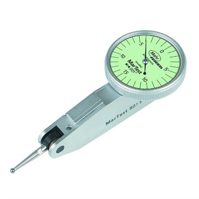
Spring force is much lower on test indicators, which may be desirable when measuring deformable materials. Test indicators are smaller and lighter than dial indicators, and these factors may be an issue in some fixtures. The dial itself on a test indicator is small, compared to those on dial indicators, so visibility is not as good. As with dial indicators, however, custom dial faces are available for test indicators for special applications.
Test indicators have generally higher resolution, but a shorter range of measurement, than dial indicators, although both factors overlap at the ends of the scales. Typical resolution (least grad) for test indicators is
.0001″ to .00005″; for dial indicators, it is .001″ to .0001″. Dial indicators usually have a total measurement range of at least .025″, and .250″ is also considered a standard figure, while longtravel units allow measurements out to several inches. The measurement range of test indicators is considerably shorter—usually between .008″ and .030″.
A few more differences to note: test indicators allow just a single revolution of the pointer around the dial (which is part of the reason for their relatively limited range of measurement), while most dial indicators allow 2.5 revolutions (or more, with revolution counters). Test indicator pointers always travel clockwise, and the dials are continuous
reading—i.e., the numbers keep ascending until the dial comes back to zero. In contrast, most dial indicators are available with either clockwise or counterclockwise motion, and offer a choice of continuous reading dials or “balanced” ones, with negative values on one side of zero, and positive values on the other.
Test indicators are extremely useful little items that are sometimes overlooked in favor of the more familiar dial indicators. When choosing between the two, it’s a matter of comparing their relative strengths and weaknesses in light of the requirements of the application.